Last update: 10.05.2025
Flutter photoframe on Raspberry Pi 4/5 with human detection, buttons. (Google photo, local storage)
Features:
- Shows a slideshow with different effects.
- Pause/Play
- Screen On/Off
- Support Image/GIF/Video
- Support 2560x1600 resolution
- [Optional] Shows media only when there are people nearby. Fall asleep if there is no movement nearby.
- [Optional/WIP] Can download photos/video from Google Photo (non-trivial setting)
- Over-the-air update (OTA)
- Support MQTT
- Web config [Work in Progress]
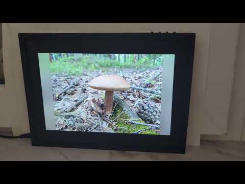


They have worse quality of display, Usually it has 720p, sometimes you can find 2K display. But the most frustration to if you leave room it demonstrates photos to a empty room. And you must power off the photoframe. Therefore, you have to manually turn off such “photoframe”, and therefore then there is no desire to turn them on, since this is an unnecessary action. Most of photoframes need to store media to usb or do a lot of action to upload new photos to a device. Of course there is no integration with smart home. And at some moment I decided to change this situation. Thus began a 5 year long story...
- Electronic components
- 1 * RaPi4 (min 1Gb) / RaPi5 + Aluminum Heatsink (min)
- [Optional] 1 * LED (something like LED Diode 5 mm)
- [Optional for LED] 3.3K Ohm resistor
- [Recommend] 4 * Button (669 min)
- [Recommend] PCB_Buttons
- [Recommend] 1 * HLK-LD2410 - 24GHz Smart Human Presence Sensing Radar Module (Ali)
- 1 * 2560*1600 Display (TFTMD089030 + Driver TC358870XBG) (Ali)
- SUPPORTED only TC358870XBG driver!
- 197.60(W) x 129.60(H) mm
- 1 * Power supply 30W min (9-30V) 5.5x2.1 (5.5.x2.5)
- 1 * Female DC Power plug 5.5х2.1mm DC-099 (Ali)
- 1 * DC-DC 9-30V -> 5V5A ( Ali )
- 1 * MicroUSB connector male (for LCD driver)
- 1 * USB Type-C connector male (for RaPi)
- 1 * HDMI - Micro-HDMI (30cm max!)
- 1 * microSDXC for Media
- Wires :) (0.75mm2, 0,12mm2, 0,07mm2)
- 8 * Dupont 2.54
- 1 * Glass - 235x170x2mm (recommend - 233х168х2, max - 234x169x2, min - 230x165x1.5)
- Glue-gun
- 2 * M2х8 Countersunk Flat Head Bolt for Body
- 2 * M2х6 Countersunk Flat Head Bolt for PCB_Buttons
- 4 * M2х3.5(3.2) brass heat set insert nut
- 2 * WAGO 3 port 2.5mm2 - Mount connection terminal WAGO 2273-203
- 1.8(1.75)mm, 3.5mm drill
- 1 * Body (Body) with tree-supports
- 1 * Screen holder (Screen Holder = SH)
- 1 * Back cover of the device (Back) with tree-supports.
- 4 * Screen retainers (Screen retainers = SR)
- 1 * Universal PCB_Buttons for buttons “PCB_dslideshow”, dslideshow - EasyEDA you can order by jlcpcb.
I recommend printing with ‘Only one wall on top surfaces’ and ‘Only one wall on first layer’. Use a 0.2mm layer.
Use tree-supports, ‘on build plate only’, ‘Support/object first layer gap’ = 0.4mm’


Download "Raspberry Pi OS Lite (64bit)" image. Run ‘rpi-imager’, select image ‘2024-11-19-raspios-bookworm-arm64-lite.img.xz’ (in my case). Change ‘Advanced options‘:
- Host name. For example ‘dslideshow1’
- ‘Enable SSH’ - set ‘Password’ or ‘Public-key’ (if you have public-kеy)
- WiFi (set correct wifi/pass)
- user/password (pi/123456)
Power on RaPi.
Wait until the RaPi connects to network. Usually it takes 1-2 minutes. Login via ssh and install all updates.
sudo apt-get update sudo apt-get upgrade
If you need to enable ssh login via password, edit the line in the file /etc/ssh/sshd_config
sudo nano /etc/ssh/sshd_config
Line:
PasswordAuthentication yes
Change configuration file ‘/boot/firmware/config.txt’
sudo nano /boot/firmware/config.txt
Add or change lines:
# disable sound
dtparam=audio=off
# disable boost
arm_boost=0
# UART on
enable_uart=1
# Bluetooth off
dtoverlay=disable-bt
# disable splash
disable_splash=1
sudo systemctl disable hciuart.service sudo systemctl disable bluealsa.service sudo systemctl disable bluetooth.service sudo systemctl stop [email protected] sudo systemctl disable [email protected]
sudo nano /boot/firmware/cmdline.txt
Add in the end of first line:
“ video=HDMI-A-1:2560x1600M@49 ”
If anything, you can check what parameters your display supports via
edid-decode /sys/class/drm/card1-HDMI-A-1/edid
,and also see if everything works correctly.
kmsprint -p
Edit file
sudo nano /boot/firmware/cmdline.txt
remove:
“console=serial0,115200 “
sudo usermod -a -G render $USER sudo usermod -a -G dialout $USER sudo usermod -a -G tty $USER
Download the archive file with
curl "https://www.raspberryconnect.com/images/scripts/AccessPopup.tar.gz" -o AccessPopup.tar.gz
unarchive with
tar -xvf ./AccessPopup.tar.gz
change to the AccessPopup folder
cd AccessPopup
Run the Installer script
sudo ./installconfig.sh
Install
1 = Install AccessPopup Script
Next
2 = Change the Access Points SSID or Password
If you don't choose: The access points wifi name (ssid) is AccessPopup and the password is 1234567890.
Set SSID:
RPiHotspot
password:
1234567890
Update OS.
sudo apt update sudo apt upgrade
Install necessary packages
sudo apt install cmake libgl1-mesa-dev libgles2-mesa-dev libegl1-mesa-dev libdrm-dev libgbm-dev ttf-mscorefonts-installer fontconfig libsystemd-dev libinput-dev libudev-dev libxkbcommon-dev
Install necessary packages for video support
sudo apt install libgstreamer1.0-dev libgstreamer-plugins-base1.0-dev libgstreamer-plugins-bad1.0-dev gstreamer1.0-plugins-base gstreamer1.0-plugins-good gstreamer1.0-plugins-ugly gstreamer1.0-plugins-bad gstreamer1.0-libav gstreamer1.0-alsa
Download last version dslideshow-7.x.x-arm64-pi4.deb Put package to home folder
/home/pi/
Create a folder 'dslideshow' in the user's home folder
cd ~/ mkdir dslideshow
change current folder
cd dslideshow
create empty file
touch config.json
Create ‘images’ folder in ‘dslideshow’ folder
mkdir images
Put a few images or videos in ‘images’
Install slideshow package.
sudo apt install ./dslideshow-7.2.0+1-arm64-pi4.deb
The system is ready to work.
- If you use RaPi5, it is advisable to purchase active cooling, preferably copper - it is thinner.
- If you use RaPi4, you need to install radiators on hot chips.
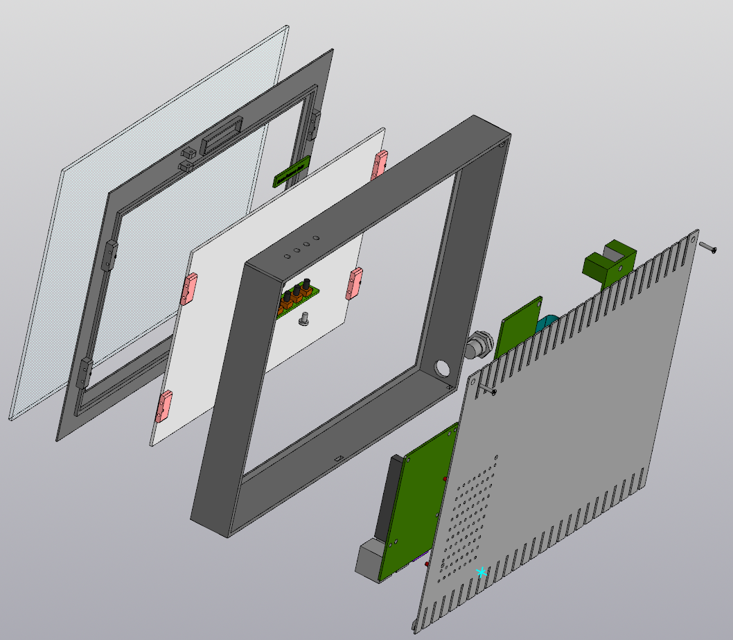
- And also remove protruding contacts in the Usb3/2 and Eth area. It is necessary so that everything fits into the case, see picture
 .
.
- And also remove protruding contacts in the Usb3/2 and Eth area. It is necessary so that everything fits into the case, see picture
-
From HLK-LD2410 - to RaPi - 400mm - 0,07мм2 * 3 pieces(+,-,Out)
-
From PCB_Buttons - to RaPi - 270mm - 0,12мм2 * 5 pieces (B1,...,Common)
-
From DC-099 - to Power pcb - 150mm - 0,75мм2 - 2 pieces (+,-)
-
From DC-099 - to Wago(p) - 120mm - 0,75мм2 - 1 pieces (-)
-
From Wago(p) - to Power pcb - 120mm - 0,75мм2 - 1 pieces (+5v)
-
From Wago(p) - to RaPi - 220mm - 0,75mm2(0,5mm2 - min) - 2 pieces (+,-)
-
From Wago(p) - to LCD Driver - 300mm - 0,75mm2(0,5mm2 - min) - 2 pieces (+,-)
-
HDMI - MicroHDMI - 300mm(30cm)
-
Cut plastic filament(1.75мм) - 22mm - 9 pieces
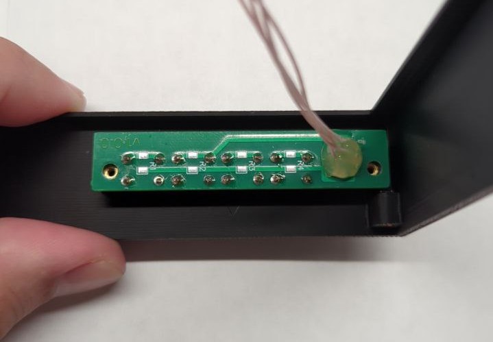
Prepare PCB_Buttons. Solder wires (0.12mm2) of the required length into the board. Solder a jumper(just a piece of wire) to the board at position R5. Solder the buttons to the board. Label each wire.(B1,B2,B3,B4,Com). It is desirable to fill all wires coming out of the board with a small amount of thermal glue. Crimp the ends of the wires with connectors (Dupont 2.54) to connect to the 40-pin GPIO header RaPi.


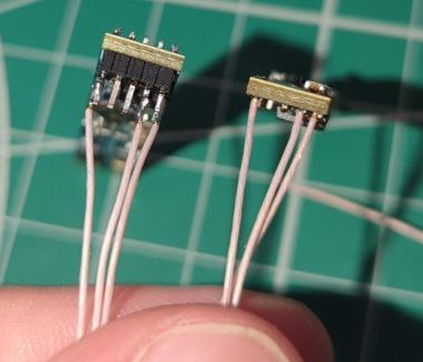
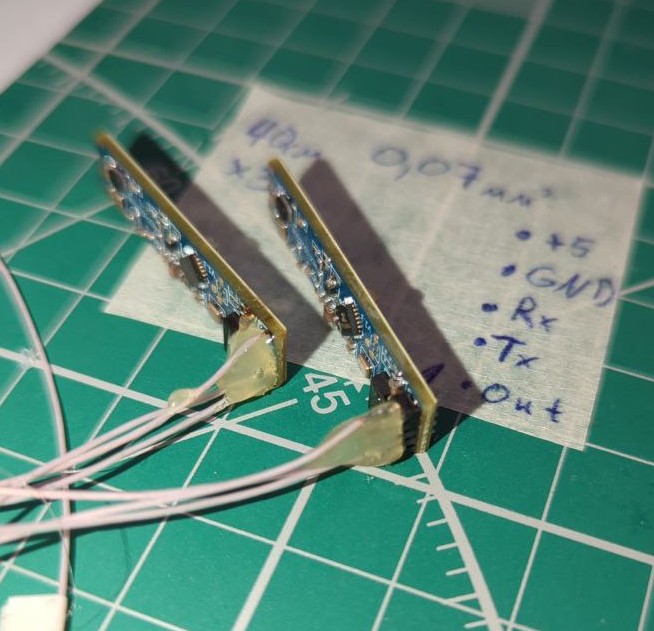
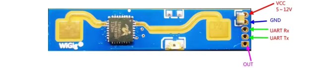
Prepare a radar(HLK-LD2410 human presence sensor), solder 3 or 5 wires (0.07mm2) of the required length to it. Label each wire (+5v,R,T,GND,Out). It is desirable to fill all wires coming out of the board with a small amount of thermal glue. The R and T wires are optional and are needed if you want to reconfigure the sensitivity of the sensor in the future.
Crimp the ends of the wires with connectors (Dupont 2.54) to connect to the 40-pin GPIO header RaPi.
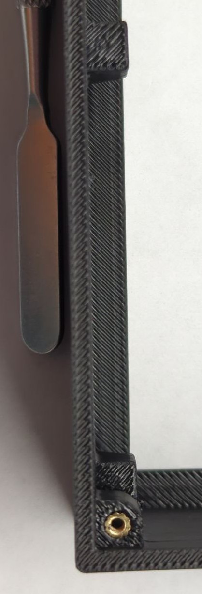
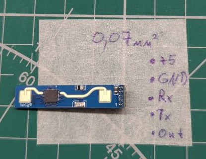 I recommend soldering the wires directly to the pins(Pictured left).
Insert 4 brass heat set insert M2 into the body.

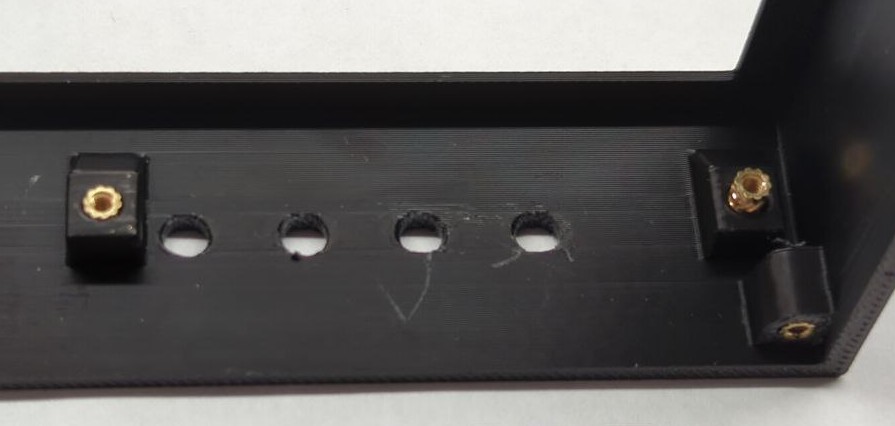 Check that the brass inserts do not protrude from the button mount holes.
 Check that the button board fits.
 If the buttons are sticking and not pressing properly, take a 3.5mm drill bit and adjust the button holes.

Prepare the screen holder(SH) and 4 screen retainers(SR), using a 1.8mm drill bit, go through all 10 holes of the SH, and 8 holes of the SR, your job is to get the filament tight enough to fit into them and not fall out!

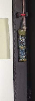
Take the screen holder (SH), place the radar (HLK-LD2410) in the special place and fix it with a glue gun, and also glue the wires coming out of the radar. Route the wires through the special holder and fix it with filament.
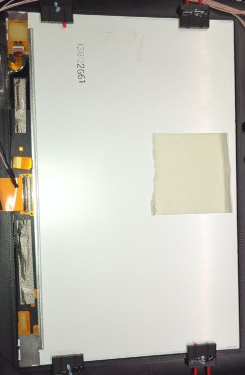
Insert the screen into the holder(SH), removing the protective film from the screen.
Fix the screen with 4 clips (SR) and filament, note that the clips have a top and bottom, the top has a key. On the left side of the SH, make the filament longer to the edge of SH or even a little more (0.5mm), it is necessary to fix the wires.
Check that the back cover fits into the grooves on the body, remove excess plastic if necessary.
Install the glass in the body. (I recommend choosing special museum glass or special glass for art galleries). Be sure to remove dust and any dirt from the inside, use microfiber.
Place the screen holder (SH) with the screen on the glass. Check that there is no dirt, and if there is, remove it.

Temporarily cover the white side of the screen with thick cardboard or paper to protect it from glue. Secure everything with a glue gun, on the 4 corners of the screen holder(SH), so that the screen holder does not fall out of the case or move around inside. Be careful not to get hot glue on the screen surface, it will burn out the screen backlight!
Mount the button board (PCB_Buttons) with 2 M2 screws. Route the wires under the SR filament on the left side. Connect all wires to RaPi. wiring diagram: dslideshow - EasyEDA
- 4 - Buttons
- (B1)Back - 16 (23 GPIO)
- (B2)Menu - 15 (22 GPIO)
- (B3)ScreenToggle -13 (27 GPIO)
- (B4)Pause - 11 (17 GPIO)
- Common - 14 (GND)
- 1 - HLK-LD2410 pins: 2(+5v), 8(R->TXD0 - 14 GPIO), 10(T->RXD0 - 15 GPIO), 6(GND), 32 (Out - 12 GPIO)

See the picture for connection, the pins for RaPi4/5 can be seen here: https://pinout.xyz/pinout/wiringpi
Check that all +5v, GND, Common are connected to the correct pins. All other pins are not connected to +3.3,+5, GND, this is important!
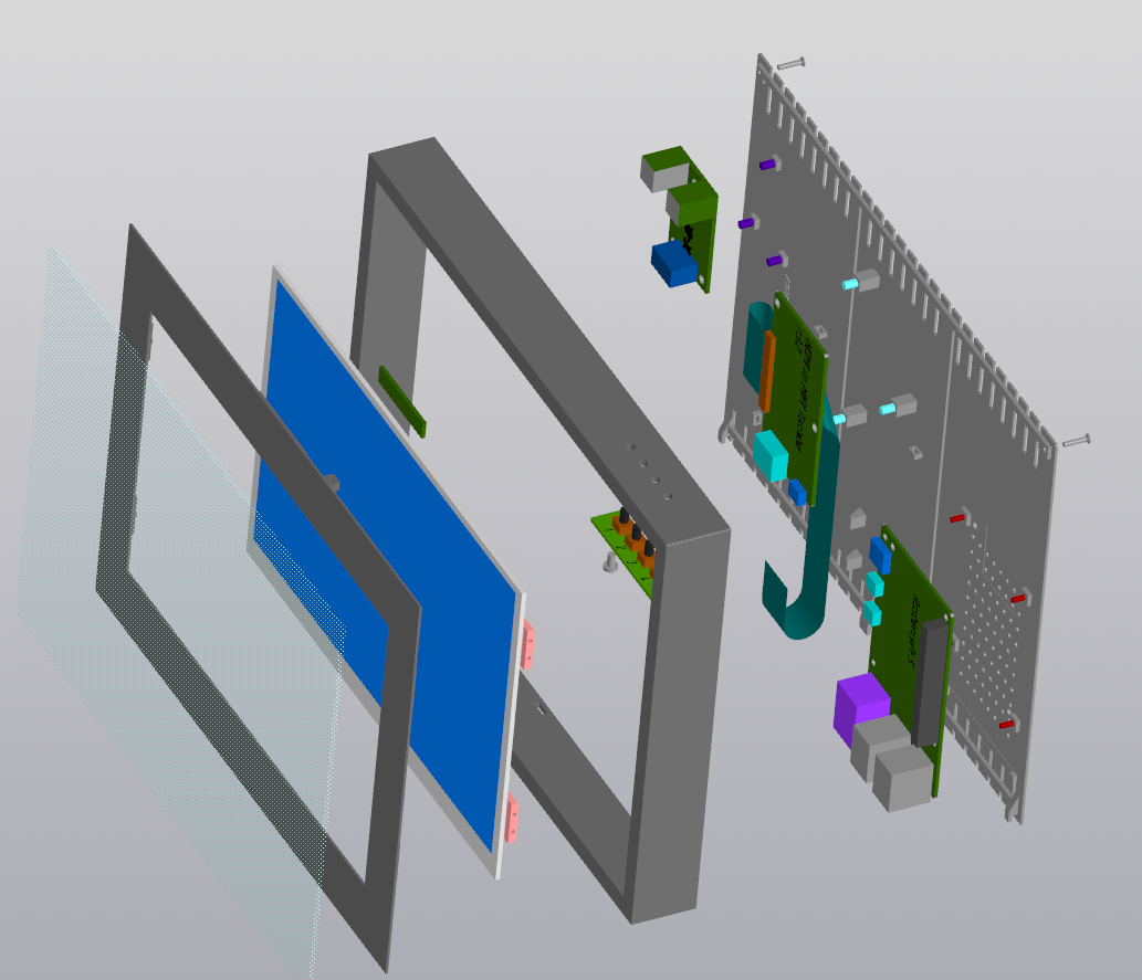
Mount all three boards into the back cover (back). Bend the cable from the driver to the display as shown in the picture, place it in the special place on the back cover.
Secure all boards with a glue gun. Apply glue to each plastic pin.

Solder usb-mini, usb-c wires of the correct length. Pay attention to V(+) and GND(-), download the specification for your USB-C boards in advance


Connect according to the diagram.

Connect RaPi and the display driver with a 30cm HDMI-microHDMI cable as shown in the picture.

Prepare the DC099 power port. Solder 2 wires to GND(-) and 1 wire to V(+). The center pin is V(+).


Insert the DC099 power port into the body, lock it.
Connect the long wires (+,-) from DC099 to Power_PCB. Connect the short wire (-) to WAGO(-) (3pin, 2.5mm2).

Before final assembly you should check that all components work, check that all +5(+) and GND(-) are correctly connected. To be sure, check the outputs on usb-c and usb-mini, this can be done with a USB tester or a multimeter.
Connect the screen and driver.

The final assembly should look like this:

Check that all USB cables are inserted, all terminals are tightened, and HDMI is fully inserted. HDMI cable is plugged into HDMI-0 on the RaPi.
Turn the system on. Check that everything is working. Shut down the system, via the photoframe menu or ssh
sudo shutdown -P now
Turn off the power. Insert the back cover into the slots in the case, tighten the 2 M2 screws.
Assembly complete.
SSH/SFTP. (sftp://[email protected]) Upload to the /home/pi/dslideshow/images/ folder.
The system supports OTA, by default the photo frame enables OTA for 1 minute after startup.
- Reboot the photo frame.
- Go to URL:
- As soon as you go to the page, the frame will switch to the mode of downloading the new firmware version, a code will be shown on the screen.
- Enter the code from the photo frame into the required field
- Attach the file with the new firmware.
- Click on the upload button and the frame will download the new firmware and update itself.
На самом деле я не люблю фоторамки. Они отвратительного качества - чаще всего 720p, в редких случаях вы получаете 2К разрешение. Но больше всего расстраивает, что когда ты уходишь, тебе надо отключать её, так как она просто будет показывать фотки в пустоту. Поэтому надо руками отключать такие “рамки”, а следовательно потом нет желания включать, так как это лишнее действие. Большинство рамок требуют записывать данные на usb, или ещё проводить кучу манипуляций для передачи фотографий на устройство. Ну и само собой, нет никакой интеграции с умным домом. И в какой-то момент я решил исправить эту ситуацию. Так началась история длинною в 5 лет…
- Electronic components
- 1 * RaPi4 (min 1Gb) / RaPi5 + Aluminum Heatsink (min)
- [Optional] 1 * LED (something like LED Diode 5 mm)
- [Optional for LED] 3.3K Ohm resistor
- [Recommend] 4 * Button (669 min)
- [Recommend] PCB_Buttons
- [Recommend] 1 * HLK-LD2410 - 24GHz Smart Human Presence Sensing Radar Module (Ali)
- 1 * 2560*1600 Display (TFTMD089030 + Driver TC358870XBG) (Ali)
- SUPPORTED only TC358870XBG driver!
- 197.60(W) x 129.60(H) mm
- 1 * Power supply 30W min (9-30V) 5.5x2.1 (5.5.x2.5)
- 1 * Female DC Power plug 5.5х2.1mm DC-099 (Ali)
- 1 * DC-DC 9-30V -> 5V5A ( Ali )
- 1 * MicroUSB connector male (for LCD driver)
- 1 * USB Type-C connector male (for RaPi)
- 1 * HDMI - Micro-HDMI (30cm max!)
- 1 * microSDXC for Media
- Wires :) (0.75mm2, 0,12mm2, 0,07mm2)
- 8 * Dupont 2.54
- 1 * Glass - 235x170x2mm (recommend - 233х168х2, max - 234x169x2, min - 230x165x1.5)
- Glue-gun
- 2 * M2х8 Countersunk Flat Head Bolt for Body
- 2 * M2х6 Countersunk Flat Head Bolt for PCB_Buttons
- 4 * M2х3.5(3.2) brass heat set insert nut
- 2 * WAGO 3 port 2.5mm2 - Mount connection terminal WAGO 2273-203
- 1.8(1.75)mm, 3.5mm drill
- 1 * Корпус (Body) с древовидными поддержками
- 1 * Держатель экрана (Screen Holder = SH)
- 1 * Заднюю крышку (Back) + с древовидными поддержками.
- 4 * Фиксаторы экрана (Screen retainers = SR)
- 1 * универсальную плату для кнопок PCB_Buttons “PCB_dslideshow”, dslideshow - EasyEDA можно заказать через jlcpcb.
Рекомендую печатать с опциями 1 периметр на первом и верхних поверхностях (‘Only one wall on top surfaces’, ‘Only one wall on first layer’), высота слоя 0.2мм.
Древовидные поддержки от стола и отступ от модели 0.4мм (‘on build plate only’, ‘Support/object first layer gap’ = 0.4mm’).
Скачиваем образ "Raspberry Pi OS Lite (64bit)" Запускаем rpi-imager выбираем образ ‘2024-11-19-raspios-bookworm-arm64-lite.img.xz’ (в моём случае), Изменяем настройки установки (‘Advanced options‘):
- Имя хоста. Например ‘dslideshow1’
- ‘Enable SSH’ - set ‘Password’ or ‘Public-key’ - установите доступ по паролю или через ключ (если он у вас есть)
- WiFi (укажите рабочий!)
- user/password (pi/123456)
Включайте оборудование.
Ждите пока система не появиться в сети. Обычно на это требуется 1-2 минуты. Заходим по ssh и ставим все обновления.
sudo apt-get update sudo apt-get upgrade
Если нужно включить вход ssh через пароль, редактируем строчку в файле /etc/ssh/sshd_config
sudo nano /etc/ssh/sshd_config
PasswordAuthentication yes
Сконфигурируйте /boot/firmware/config.txt
sudo nano /boot/firmware/config.txt
Добавте или измените следующие строки
# disable sound
dtparam=audio=off
# disable boost
arm_boost=0
# UART on
enable_uart=1
# Bluetooth off
dtoverlay=disable-bt
# disable splash
disable_splash=1
sudo systemctl disable hciuart.service sudo systemctl disable bluealsa.service sudo systemctl disable bluetooth.service sudo systemctl stop [email protected] sudo systemctl disable [email protected]
sudo nano /boot/firmware/cmdline.txt
Добавить в конце первой строчки:
“ video=HDMI-A-1:2560x1600M@49 ”
Если что можете проверить какие ваш дисплей поддерживает параметры через
edid-decode /sys/class/drm/card1-HDMI-A-1/edid
,а также посмотреть всё ли работает корректно.
kmsprint -p
отредактируйте файл
sudo nano /boot/firmware/cmdline.txt
удалите данный текст
“console=serial0,115200 “
sudo usermod -a -G render $USER sudo usermod -a -G dialout $USER sudo usermod -a -G tty $USER
Скачайте архив
curl "https://www.raspberryconnect.com/images/scripts/AccessPopup.tar.gz" -o AccessPopup.tar.gz
Распакуйте
tar -xvf ./AccessPopup.tar.gz
Перейдите в папку
cd AccessPopup
Запустите скрипт настройки
sudo ./installconfig.sh
Выберите вначале.
1 = Install AccessPopup Script
Далее
2 = Change the Access Points SSID or Password
Если не выбрать то: The access points wifi name (ssid) is AccessPopup and the password is 1234567890.
Установите SSID:
RPiHotspot
Пароль:
1234567890
обновим все пакеты системы.
sudo apt update sudo apt upgrade
установим зависимости для работы приложения
sudo apt install cmake libgl1-mesa-dev libgles2-mesa-dev libegl1-mesa-dev libdrm-dev libgbm-dev ttf-mscorefonts-installer fontconfig libsystemd-dev libinput-dev libudev-dev libxkbcommon-dev
установим зависимости для видео
sudo apt install libgstreamer1.0-dev libgstreamer-plugins-base1.0-dev libgstreamer-plugins-bad1.0-dev gstreamer1.0-plugins-base gstreamer1.0-plugins-good gstreamer1.0-plugins-ugly gstreamer1.0-plugins-bad gstreamer1.0-libav gstreamer1.0-alsa
Скачайте последнюю версию dslideshow-7.x.x-arm64-pi4.deb залейте её в корень домашней папки
/home/pi/
Создайте ‘dslideshow’ в корне
cd ~/ mkdir dslideshow
создайте пустой файл
config.json
создайте папку
images
поместите пару картинок или видео mp4 в папку images.
Установите пакет.
sudo apt install ./dslideshow-7.2.0+1-arm64-pi4.deb
Система готова к работе.
- Если вы используете RaPi5 желательно приобрести активное охлаждение, желательно медное - оно тоньше.
- Если вы используете RaPi4 то надо установить радиаторы на горячие чипы.
- А также удалить выступающие контакты в области Usb3/2 и Eth. Это нужно чтобы всё влезло в корпус, см картинки .
- А также удалить выступающие контакты в области Usb3/2 и Eth. Это нужно чтобы всё влезло в корпус, см картинки
-
От HLK-LD2410 - до RaPi 400mm -0,07мм2 * 3 шт(+,-,Out)
-
От PCB_Buttons - до RaPi 270mm - 0,12мм2 * 5 шт (B1,...,Common)
-
От DC-099 - до Power pcb - 150mm - 0,75мм2 - 2 шт (+,-)
-
От DC-099 - до Wago(p) - 120mm - 0,75мм2 - 1 шт (-)
-
От Wago(p) - до Power pcb - 120mm - 0,75мм2 - 1шт (+5v)
-
От Wago(p) - до RaPi - 220mm - 0,75мм2(0,5mm2 - min) - 2шт (+,-)
-
От Wago(p) - до LCD Driver 300mm - 0,75мм2(0,5mm2 - min) - 2шт (+,-)
-
HDMI - MicroHDMI - 300mm(30cm)
-
Отрежьте филамент(1.75мм) - 22mm - 9шт
Подготовьте плату с кнопками. Впаяйте в плату провода(0.12мм2) нужной длины. Припаяйте перемычку(просто кусочек провода) на плату в позицию R5. Припаяйте кнопки к плате. Каждый провод промаркируйте.(B1,B2,B3,B4,Com). Желательно все провода выходящие с платы залить небольшим кол-вом термоклея. Концы проводов обожмите коннекторами(Dupont 2.54) для присоединения к 40-pin GPIO header RaPi.
Подготовьте радар(сенсор присутствия людей HLK-LD2410), припаяйте к нему 3 или 5 проводов(0.07мм2) нужной длины. Каждый провод промаркируйте(+5v,R,T,GND,Out). Желательно все провода выходящие с платы залить небольшим кол-вом термоклея. Провода R и T опциональные и нужны если вы хотите перенастраивать чувствительность сенсора в будущем.
Концы проводов обожмите коннекторами(Dupont 2.54) для присоединения к 40-pin GPIO header RaPi.
Я рекомендую припаивать провода прямо к выводам, так как при выпаивании выводов можно повредить плату.(На фото слева)
Впаяйте в корпус 4 латунные вставки М2.
Проверьте, что латунные вставки не выпирают в креплениях кнопок.
Проверьте, что плата с кнопками подходит.
Если кнопки заедают и плохо нажимаются, возьмите сверло на 3.5мм и подкорректируйте отверстия для кнопок.
Подготовьте держатель экрана(SH) и 4 фиксатора экрана(SR), с помощью сверла 1.8мм, пройдитесь по всем 10 отверстиям SH, и по 8 отверстиям(SR), ваша задача чтобы филамент достаточно плотно заходил в них и не выпадал!
Возьмите держатель экрана(SH), установите радар (HLK-LD2410) в нужное место и зафиксируйте клеевым пистолетом, а также прихватите клеем и провода выходящие из радара. Проложите провода через специальный держатель и зафиксируйте его филаментом.
Установите экран в держатель(SH), предварительно удалив защитную плёнку с экрана.
Зафиксируйте экран с помощью 4-х фиксаторов(SR) и нитей филамента, обратите внимание что фиксаторы имеют верх и низ, вверху есть ключ. У фиксаторов слева сделайте филамент подлиннее до края SH или даже может чуть больше(0.5мм), это нужно для фиксации проводов.
Проверьте что задняя крышка входит в пазы в корпусе, при необходимости уберите лишний пластик.
Установить стекло в корпус. (рекомендую выбрать специальное музейное стекло или специально стекло для картинных галерей). Обязательно удалите пыль и всякие загрязнения с внутренней стороны, используйте микрофибру.
Поместите держатель экрана(SH) с экраном на стекло. Проверьте что нет грязи, если есть удалите.
Временно прикройте белую сторону экрана толстым картоном или бумагой от клея. Зафиксировать всё клеевым пистолетом, по 4-ём углам держателя экрана(SH), так чтобы держатель экрана не выпадал из корпуса и не двигался внутри. Будьте осторожны, нельзя чтобы горячий клей попал на поверхность экрана, это приводит к выгоранию подсветки экрана!
Установите плату с кнопками (PCB_Buttons) с помощью 2х M2 винтов. Провода проложите под филаментом SR с левой стороны. Подсоедините все провода к RaPi. схема подключения: dslideshow - EasyEDA
- 4 - Buttons
- (B1)Back - 16 (23 GPIO)
- (B2)Menu - 15 (22 GPIO)
- (B3)ScreenToggle -13 (27 GPIO)
- (B4)Pause - 11 (17 GPIO)
- Common - 14 (GND)
- 1 - HLK-LD2410 pins: 2(+5v), 8(R->TXD0 - 14 GPIO), 10(T->RXD0 - 15 GPIO), 6(GND), 32 (Out - 12 GPIO)
Смотри картинку для подключения, пины для RaPi4/5 можно посмотреть тут: https://pinout.xyz/pinout/wiringpi
Проверьте что все +5v, GND, Common подсоединены к нужным пинам. Все другие пины не подсоединены к +3.3,+5, GND, это важно!
Установите все три платы в заднюю крышку (back). Согните шлейф от драйвера к дисплею как показано на картинке, поместите его в специальное место на задней крышке.
Зафиксируйте клеевым пистолетом все платы. Нанесите клей на каждый пластиковый штырёк и проведите клеем до основания задней крышки, для лучшей фиксации.
Спаяйте usb-mini, usb-c провода нужной длинны. Обратите внимание на полярность, скачайте заранее спецификацию для ваших плат USB-C
Соедините по схеме.
Соедините RaPi и драйвер дисплея 30см кабелем HDMI-microHDMI, как показано на картинке.
Подготовьте порт питания DC099. Припаяйте 2 провода на (-) и 1 провод на (+). Центральный пин это (+).
Вставьте порт питания DC099 в корпус, зафиксируйте его в корпусе.
Присоедините длинные провода(+,-) от DC099 к Power_PCB. Короткий провод (-) подключите к WAGO(-) (3pin, 2.5mm2).
Перед окончательной сборкой нужно проверить что все компоненты работают, проверьте что все (+) и (-) корректно соединены. Для верности проверьте выходы на Usb-c и usb-mini, это можно сделать через USB тестер или через мультиметр.
Соедините шлейфом экран и драйвер.
Итоговая сборка должна выглядеть так:
Проверьте что все USB кабели вставлены, все клеммы затянуты, HDMI вставлен до конца. HDMI кабель воткнут в HDMI-0 на RaPi.
Включите систему. Проверьте что всё работает. Выключите систему, через меню рамки или через ssh
sudo shutdown -P now
Выключите питание. Вставьте заднюю крышку в пазы в корпусе, закрутите 2 винта М2.
Сборка завершена.
Через SSH\SFTP. (sftp://[email protected]) Заливайте в папку /home/pi/dslideshow/images/
Система поддерживает OTA, по умолчанию рамка включает OTA на 1 минуту после старта.
-
Перезагружаете фоторамку.
-
Заходите по URL:
-
Как только вы перейдёте на страницу, рамка переключится в режим загрузки новой версии прошивки, на экране будут показаны код-цифры.
-
Введите код с фоторамки в нужное поле
-
Прикрепите файл с новой прошивкой
-
Нажмите на кнопку upload и рамка загрузит новую прошивку и сама себя обновит.